MIG Welding Applications in Oil and Gas Pipelines
MIG welding for pipelines combines speed, precision, and process flexibility to meet the structural and safety demands of oil and gas infrastructure.
This guide covers the techniques, parameters, codes, and inspection methods that pipeline professionals in the Mountain West rely on, from new construction to maintenance welding on existing systems.
Key Takeaways
MIG welding (GMAW) is the industry standard for pipeline fabrication due to its speed, consistency, and material versatility.
Transfer mode selection, short circuit, pulsed MIG, or spray directly impacts quality on thin and heavy-wall pipe.
Shielding gas selection and parameter control are critical to corrosion resistance and structural integrity.
API 1104, ASME B31.8, and AWS certifications are required for regulated pipeline welding projects.
Radiographic and ultrasonic testing verify weld integrity before any pipeline enters service.
Automated orbital MIG systems are raising quality benchmarks across pipeline fabrication.
What Is MIG Welding for Pipelines?
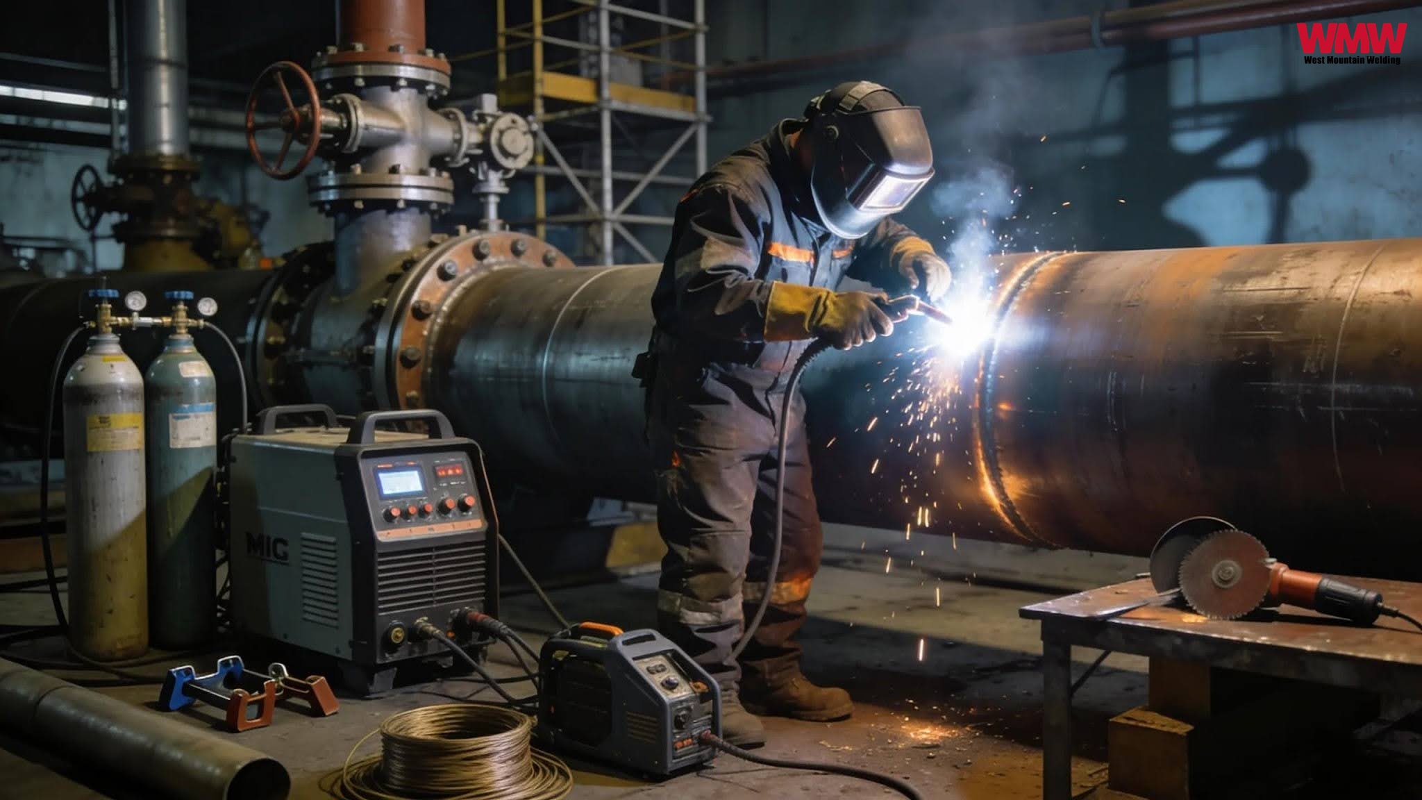
MIG welding formally Gas Metal Arc Welding (GMAW), uses a continuous wire electrode fed through a welding gun alongside a shielding gas to produce strong, repeatable welds on steel pipe. The process is semi-automatic: the wire feeds continuously at a set rate while the welder controls travel speed, gun angle, and positioning.
In oil and gas applications, it's valued for high deposition rates, adaptability across material thicknesses, and straightforward integration with automated and mechanized systems. Pipeline welders on transmission lines, gathering systems, and distribution piping rely on MIG processes because they balance productivity with the tight quality tolerances that high-pressure service demands.
Compared to shielded metal arc welding (SMAW), GMAW reduces arc-off time between electrode changes and supports faster fill and cap passes, a meaningful advantage on production pipeline runs where schedule is a cost driver.
MIG Welding Techniques for Pipeline Fabrication
Choosing the right transfer mode is one of the most consequential decisions in pipeline weld procedure development.

Short Circuit Transfer
limits heat input and controls the heat-affected zone (HAZ), making it ideal for thin-wall pipe, out-of-position welds, and maintenance, repair work where base metal condition may already be compromised.
Pulsed MIG Welding
alternates between high and low current pulses for precise heat control, critical for preventing burn-through on thin-walled pipe and alloy materials. It also reduces spatter, cutting post-weld cleanup time.
Spray Transfer
delivers smooth, high-deposition beads on heavier wall sections in flat or horizontal positions. It's commonly specified for fill and cap passes on large-diameter transmission pipe.
Each technique suits different pipe grades, wall thicknesses, and weld positions, making transfer mode selection a core part of any qualified welding procedure specification (WPS).
How MIG Welding Protects Pipeline Structural Integrity
Pipeline failures in oil and gas service are frequently traced to weld defects, inadequate shielding, or improper heat management. Properly executed MIG welding addresses each of these risks.
Shielding Gas is the first line of defense against oxidation and porosity. Argon/CO₂ blends, commonly 75/25 for standard carbon steel and 90/10 for pulsed and spray transfer, are the industry standard. For stainless and duplex alloys in sour service, tri-mix gases (Ar/He/CO₂) protect against sensitization and intergranular corrosion.
Joint Preparation is equally critical. Full-penetration groove welds on properly beveled butt joints provide the structural foundation needed to withstand operating pressures, thermal cycling, and ground movement over the pipeline's service life.
Automation eliminates the variability inherent in manual welding during production runs. Automated MIG systems deposit each pass at consistent parameters, reducing defect rates and minimizing the repairs that delay commissioning.
Welding Parameters That Determine Pipeline Weld Quality
Code compliance starts with disciplined parameter control. The table below covers the core variables that pipeline welders and inspectors monitor against the qualified WPS.
Key Welding Parameters and Their Effects
Wire Feed Speed (150–450 IPM)
Controls the deposition rate and influences the overall bead profile.
Voltage (18–32V)
Determines arc length and affects bead width and weld appearance.
Travel Speed (10–20 IPM)
Impacts heat input, penetration depth, and weld consistency.
Shielding Gas Flow (30–50 CFH)
Protects the weld pool from atmospheric contamination and oxidation.
Electrode Extension (CTWD) (¾"–1")
Influences both deposition rate and heat input, affecting weld quality and efficiency.
For field pipeline welding, engine-driven machines with constant-voltage MIG output are standard. They must maintain stable arc characteristics across variable environmental conditions, wind, temperature, and generator load fluctuation, all of which affect arc quality in the field.
Pipeline Welding Codes and Certifications That Apply to MIG Work

Pipeline welding is tightly regulated. Qualification requirements apply at the procedure level, the welder level, and the inspection level; all three must be in order before production welding starts.
API 1104 is the primary standard governing pipeline welding in North America. It establishes requirements for welding procedure specifications (WPS), procedure qualification records (PQR), welder performance qualification, and acceptance criteria for inspection and testing. All regulated pipeline operators require API 1104-qualified procedures.
ASME B31.8 governs gas transmission and distribution piping, referencing API 1104 for welding and adding system-level design requirements that affect joint efficiency ratings and pressure testing.
ASME B31.4 applies to hazardous liquid pipelines, crude oil, refined products, and NGL systems with API 1104 as the governing welding standard.
AWS D1.1 applies to structural attachments, supports, and above-grade components. AWS Certified Welder (CW) credentials in GMAW are often required alongside API 1104 qualification, particularly for Utah-based EPC contractors working on mixed structural and pipeline scopes.
In the Mountain West, some state utility commissions impose additional qualification requirements for intrastate gas distribution systems. Welders working across multiple projects should confirm state-specific requirements with each operator before mobilizing.
Weld Inspection Methods for Oil and Gas Pipelines
Every pressure-containing weld must be verified before a pipeline goes into service. Inspection scope and method depend on pipe service classification and the applicable code.
Visual Inspection (VT) is the baseline for checking the weld profile, undercut, overlap, and surface-breaking discontinuities. All pipeline welds receive VT; additional NDE is layered on based on code requirements.
Radiographic Testing (RT) uses X-ray or gamma-ray imaging to detect internal flaws, including porosity, slag, lack of fusion, and cracks. RT is the most common volumetric method for cross-country pipeline girth welds under API 1104.
Automated Ultrasonic Testing (AUT) is increasingly specified on large-diameter pipelines as an alternative or supplement to RT. AUT provides dimensional sizing data on detected flaws, supporting fitness-for-service assessments.
Hydrostatic Testing pressurizes the completed pipeline section with water to verify leak-tightness and confirm structural integrity at or above the maximum allowable operating pressure (MAOP). It's a system-level acceptance test, not a weld-by-weld check.
Pre-weld documentation, in-process hold points, and third-party certified welding inspector (CWI) oversight are standard practice on regulated projects. Closeout packages NDE reports, repair records, hydro test results, and as-built documentation, support future integrity management program (IMP) activities required under DOT pipeline safety regulations.
Pipeline Welding Safety Practices That Reduce Risk on Every Job
Pipeline welding in oil and gas environments carries hazards beyond the welding process itself. Confined spaces, residual hydrocarbons, remote field locations, and high-pressure testing all add complexity that must be managed systematically.
A job hazard analysis (JHA) specific to the welding scope should be completed before mobilization. For tie-ins on in-service lines, hot-work permits and continuous atmospheric gas monitoring are mandatory. Welders working in oil and gas environments should be trained not just in process skills but in atmospheric hazard recognition and emergency response for hot-work incidents.
Minimum PPE requirements on pipeline sites include auto-darkening welding helmets, flame-resistant (FR) clothing, leather welding gloves, and respiratory protection appropriate to the fume profile of the base and filler metals in use. Routine safety audits catch procedural drift, the gradual relaxation of safe practices that tends to develop on long-duration projects, and reinforce a culture where welders are accountable for safety outcomes alongside productivity.
Automated and Orbital MIG Welding on Pipeline Projects
Manual MIG welding has practical limits on full circumferential pipe welds, as stopping and restarting around a joint introduces potential defect sites at every restart location. Automated orbital MIG systems solve this directly by eliminating manual restarts on girth welds entirely.
Orbital welding heads clamp to the pipe and rotate continuously around the joint, depositing each pass at parameters controlled by a programmable welding system. Studies on automated orbital MIG welding of AISI 1020 mild steel confirm superior tensile strength and hardness uniformity versus manual techniques, a meaningful advantage in high-cycle pressure service where fatigue performance matters alongside static strength.
Key benefits for pipeline fabrication include consistent heat input and bead geometry on every weld, lower rework rates, faster cycle times on production runs, reduced reliance on individual welder skill for pass-to-pass repeatability, and real-time parameter logging that supports WPS compliance documentation and traceability. Spool fabrication shops in the Mountain West are actively adopting semi-automated and orbital MIG systems for structural pipe fabrication, while field applications continue to expand as access geometry and project economics allow.
West Mountain Welding: Pipeline MIG Welding in Utah and the Mountain West
West Mountain Welding provides qualified pipeline welders, code-compliant procedures, and thorough inspection documentation for oil and gas projects across Utah and the Mountain West. Whether you need certified welders for a new transmission line, repair welding on existing infrastructure, or a trusted fabrication partner for your EPC scope, our team has the API 1104 qualifications and field experience to deliver work that passes inspection the first time.
Contact West Mountain Welding to discuss your pipeline welding requirements.
Frequently Asked Questions: MIG Welding for Pipelines
1. What is MIG welding used for in oil and gas pipelines?
MIG welding (GMAW) is used for root, fill, and cap passes on pipeline girth welds, structural attachments, above-grade piping fabrication, and maintenance and repair welds. Its speed and adaptability make it suitable for both shop fabrication and field pipeline construction.
2. Is MIG welding code-approved for oil and gas pipelines?
Yes. GMAW is fully accepted under API 1104, ASME B31.8, and ASME B31.4 when performed under a qualified WPS by a qualified welder. Many operators specify MIG for fill and cap passes because of its productivity advantages over SMAW.
3. What certifications do pipeline MIG welders need?
API 1104 welder qualification is the minimum for regulated pipeline work. AWS Certified Welder (CW) credentials are commonly required for structural scopes. State-specific requirements may apply depending on the system and operator.
4. What shielding gas is best for pipeline MIG welding?
A 75/25 Argon/CO₂ blend is standard for carbon steel pipeline welding, good penetration, low spatter, and reliable arc stability. A 90/10 blend is preferred for pulsed MIG and spray transfer applications.
5. How is pipeline MIG weld quality verified?
Through visual inspection, radiographic or automated ultrasonic testing, and hydrostatic pressure testing. Acceptance criteria are specified by API 1104 and the pipeline operator's project specification.